Power System-II (2022) SOLUTION
WhatsApp Group link- https://chat.whatsapp.com/LgIUEkpIp3l1xKOzWSSpct
ELECTRICAL ENGINEERING
2(a).with neat flow chart, explain the load flow study using n-r power flow method. How does the method get modified when PV buses are also present?
Load flow study is a crucial aspect of power system analysis, providing valuable insights into the system’s steady-state operation. The Newton-Raphson (NR) method is a widely used technique for conducting load flow studies due to its efficiency and robustness.
Load Flow Study using N-R Power Flow Method
The NR method is an iterative technique that utilizes the concept of linearization to solve the non-linear power flow equations. It involves the following steps:
- Initialize: Assume initial voltage magnitudes and angles for all buses.
- Calculate power mismatches: For each bus, compute the difference between the scheduled and calculated real and reactive power injections.
- Form Jacobian matrix: Construct the Jacobian matrix, which represents the sensitivity of power mismatches to changes in voltage magnitudes and angles.
- Solve linear equations: Solve the linearized system of equations using matrix inversion or other suitable techniques.
- Update voltage values: Update the voltage magnitudes and angles based on the solution obtained in step 4.
- Convergence check: Check if the power mismatches have converged to an acceptable level. If not, repeat steps 2 to 5 until convergence is achieved.
Modification for PV Buses
When PV buses (buses with specified real power generation and voltage magnitude) are present, the NR method requires a slight modification. The power mismatch equations for PV buses are modified to consider the fixed real power generation and voltage magnitude constraints.
- Real power mismatch equation: For PV buses, the real power mismatch equation is replaced with a constraint equation that enforces the specified real power generation.
- Reactive power mismatch equation: For PV buses, the reactive power mismatch equation remains the same, but the reactive power injection is treated as an unknown variable.
- Jacobian matrix modification: The Jacobian matrix is modified to incorporate the new constraint equation and treat the reactive power injection at PV buses as an unknown variable.
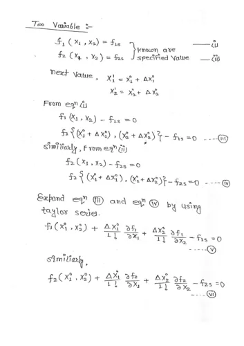
2.(b)derive the equation of various element of jacobian matrix in case of newton rapshon method.

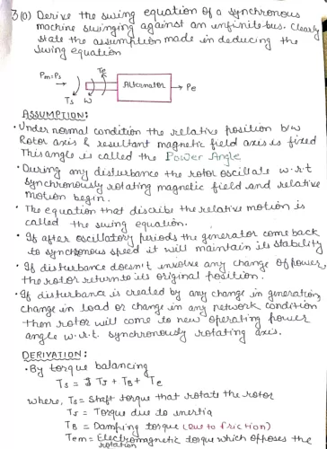
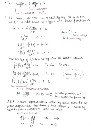
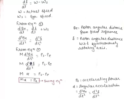
3(a). Derive the saving equation of a synchronous machine swinging against an infinite bus Clearly state the assumptions made in deducing the swing equation.
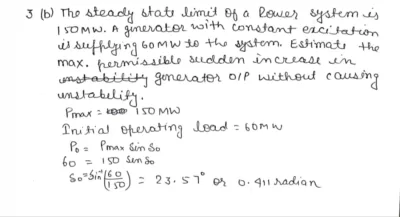
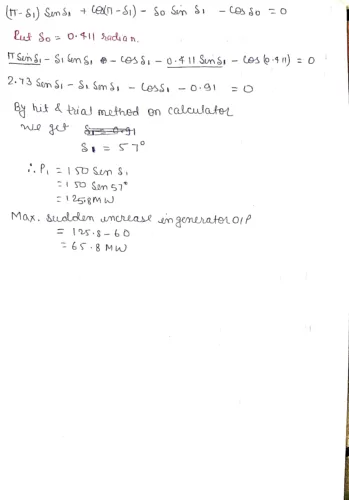
3(b). The steady state limit of a power system is 150 MW. A generator with constant excitation is supplying 60 MW to the system. Estimate the maximum permissible sudden increase in generator output without causing instantly.

4.(a). what are the different method of voltage control in a power system? Explain the working of an on load tap changing transformer.
Maintaining voltage stability is crucial for the reliable operation of power systems. Voltage fluctuations can lead to equipment damage, power outages, and even system collapse. Therefore, various methods are employed to control voltage levels within acceptable limits.
Voltage Control Methods
- On-load tap changing (OLTC) transformers: OLTC transformers adjust the turns ratio of their windings to regulate voltage levels. This is achieved by physically changing the tap connections on the transformer windings while the transformer is in operation, allowing for continuous voltage adjustment without interrupting power supply.
- Shunt reactors: Shunt reactors are inductive devices connected in parallel with the power lines. They absorb reactive power, reducing voltage drops and improving voltage regulation, particularly in long transmission lines.
- Shunt capacitors: Shunt capacitors are capacitive devices connected in parallel with the power lines. They inject reactive power, raising voltage levels and improving voltage regulation, particularly near load centers.
- Static VAR compensators (SVCs): SVCs are thyristor-controlled reactive power sources that can provide both inductive and capacitive compensation. They offer fast and flexible voltage control, making them versatile tools for maintaining system stability.
- Synchronous condensers: Synchronous condensers are rotating machines that act as variable sources of reactive power. They can inject or absorb reactive power, providing voltage support and improving system stability.
Working of an On-Load Tap Changing Transformer
- An OLTC transformer consists of multiple windings, each with several taps. By switching between different tap connections, the effective turns ratio of the transformer is altered. This adjustment in turns ratio changes the voltage ratio between the primary and secondary windings, thereby regulating the voltage level on the secondary side.
- The tap-changing mechanism of an OLTC transformer typically employs a moving contact arm that selects different taps on the transformer windings. This arm is actuated by a control system that monitors the voltage on the secondary side and initiates tap changes whenever necessary.
- OLTC transformers are equipped with protective devices to prevent damage during tap-changing operations. These devices ensure that the tap-changing mechanism operates safely and reliably without interrupting the power flow.
- OLTC transformers are widely used in power transmission and distribution systems due to their ability to continuously regulate voltage levels without interrupting power supply. They play a critical role in maintaining system stability and ensuring reliable power delivery.
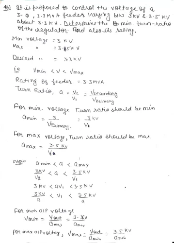
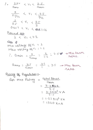
4(b). It is proposed to control the voltage of a 3-phase , 3-3 MVA feeder, 3-3 varying between 3kV and 3-5 kV about 3-3 kV. Determine the minimum turn ratio of the regular. Find also its rating,
5(a). what do you mean by power system secuirity analysis? Explain using the power system state transition diagram.
The study and evaluation of a power system’s capacity to tolerate and recover from diverse disruptions while preserving its stability and dependability is known as power system security analysis. The intention is to guarantee that, in the face of unforeseen circumstances or modifications to operational parameters, the power system will continue to function within reasonable bounds.
An illustration of the many states and transitions a power system might experience under both normal and abnormal operating situations is called a power system state transition diagram. It is a helpful tool for assessing the security and stability of the power network and aids in understanding the dynamic behavior of the system.
Here’s a brief explanation using a simplified Power System State Transition Diagram:
Normal Operating State (NOS):
- This is the base state where the power system operates under normal conditions.
- All generators are synchronized, and the system is in a stable equilibrium.
Disturbance (D):
- Disturbances can occur due to various reasons such as equipment failures, lightning strikes, or sudden changes in demand.
- The system transitions from the normal operating state to a disturbed state.
Transient State (TS):
– After a disturbance, the system enters a transient state characterized by rapid changes in voltages and currents.
– Protective devices and control systems act to mitigate the impact of the disturbance.
Stable State (SS)
– If the system successfully recovers from the transient state, it enters a stable state.
– The voltages and currents return to acceptable levels, and the system regains its equilibrium.
Unstable State (US):
– If the system fails to recover and stabilize, it may enter an unstable state.
– In this state, voltages and currents continue to deviate from the desired values, leading to a potential blackout.
Emergency State (ES):
– In the case of an unstable state, the system transitions into an emergency state.
– Emergency control actions, such as load shedding or reconfiguration of the network, may be taken to prevent a cascading failure.
The Power System State Transition Diagram helps power system operators and planners understand the sequence of events during disturbances, identify critical points, and develop strategies to enhance the system’s security and resilience. It’s an essential tool for maintaining a reliable and stable power supply in the face of various challenges.
5.(b) A 3-phase transmission line has a reactance of 15 ohm per phase. The voltage at each end is maintained at 66 kV (line-to-line). Determine the maximum steady-state power that can be transmitted by the line. Also determine the limits of angular oscillation for transient stability, when the above line develops a sudden jerk at 3/5th of the steady-state limit.

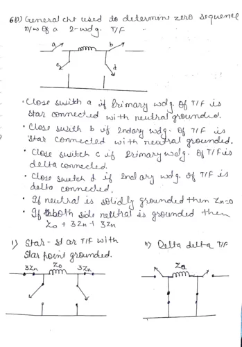
6.(a) Draw a general circuit, which can br used to determine the zero sequence network of a two-winding transformer Draw the zero sequence network of (i) star-star transformer with star-point grounded and (ii) delta-delta transformer.
6(b).A single-phase load of 100 kVA is connected across lines bc of a 3-phase supply of 3.3 kV. Determine symmetrical components of line current.

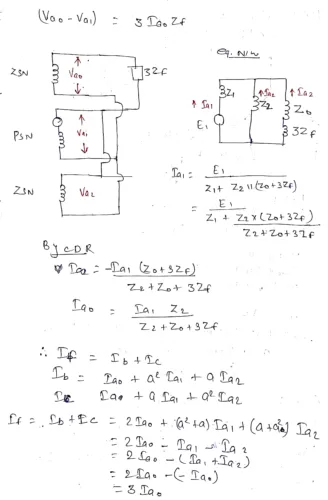
7(a) Derive the necessary equation to determine the fault current for an L-L-G fault. Draw a diagram showing the interconnection of sequence network.

7.(b). The per unit values of positive, negative and zero sequence reactances of a network at fault are 0.16, 0.14 and 0.2. Determine the fault current, if fault is double line to ground.
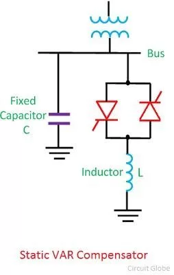
8(a) Explain the function of a 3 phase static VAR compensator with necessary diagram
A three-phase static VAR compensator (SVC) is a crucial component in modern power systems, regulating voltage, power factor, and improving system stability.
Function:
- Voltage Regulation: The SVC injects or absorbs reactive power to maintain desired voltage levels at a specific point in the grid.
- Power Factor Correction: By adjusting reactive power, the SVC minimizes reactive power flow and improves overall power factor.
- Stability Enhancement: SVCs offer dynamic voltage support during disturbances, stabilizing voltage fluctuations and preventing voltage collapse.
- Harmonic Mitigation: SVCs suppress harmonics generated by non-linear loads, improving power quality.
Components:
- Thyristor Controlled Reactor (TCR): continuously adjusts reactive power by controlling the firing angle of thyristors connected in series with a reactor.
- Thyristor Switched Capacitor (TSC): provides discrete steps of reactive power by switching capacitors in and out of the circuit using thyristors.
- Fixed capacitors and reactors: provide a base level of reactive power compensation.
Diagram:
Operation:
The SVC continuously monitors the voltage at the connection point. Depending on the voltage deviation:
- Low voltage: SVC acts as a capacitor, injecting reactive power into the system.
- High voltage: SVC acts as an inductor, absorbing reactive power from the system.
By adjusting the firing angle of the TCR and switching the TSC capacitors, the SVC precisely controls the reactive power injected or absorbed, ensuring voltage stability and optimal power quality.
Overall Advantages:
- Improves voltage profile
- Increases power transfer capacity
- Reduces losses
- Enhances system stability
- Mitigates voltage flicker and harmonics
The SVC plays a vital role in modern power systems, ensuring a reliable and efficient electricity supply.
8(b) Explain the function of an automatic voltage regulator. what qualities should an automatic voltage regulator have?
An automatic voltage regulator (AVR) is an electronic device that automatically maintains a constant voltage level to electrical equipment despite fluctuations in the input voltage. It is commonly used in generators, power supplies, and other applications where a stable voltage is critical.
Function of an Automatic Voltage Regulator
An AVR continuously monitors the output voltage of the power source and compares it to a reference voltage. If the output voltage deviates from the reference voltage, the AVR generates a control signal that adjusts the voltage regulator to bring the output voltage back to the desired level.
Qualities of an Automatic Voltage Regulator
An effective AVR should possess several key qualities:
- Accuracy: The AVR should maintain the output voltage within a narrow tolerance range, typically around ±1%.
- Response time: The AVR should respond quickly to voltage fluctuations, minimizing the duration of any voltage deviations.
- Regulation range: The AVR should be able to compensate for a wide range of input voltage variations.
- Reliability: The AVR should be robust and reliable, operating consistently under various load conditions and environmental factors.
- Efficiency: The AVR should operate efficiently, minimizing power losses and heat generation.
- Protection: The AVR should incorporate protective features to safeguard itself and the connected equipment from overvoltage, undervoltage, overcurrent, and other fault conditions.
- Versatility: The AVR should be compatible with various power sources and load types.
- Cost-effectiveness: The AVR should offer a balance between performance and cost-efficiency.
9.Write short Notes on the following..
(a). SCADA System (b). Equal area Criterion.
(a). SCADA System
Supervisory Control and Data Acquisition (SCADA) systems are automated control systems used to monitor and control industrial processes, such as those in manufacturing, power generation, and water treatment. These systems collect data from sensors and other devices in the field, and then use that data to control actuators and other equipment. SCADA systems can be used to automate a wide range of tasks, from simple ones like turning on and off pumps to complex ones like controlling the temperature and pressure in a chemical reactor.
Components of a SCADA system:
- Sensors: Collect data from the field, such as temperature, pressure, and flow rate.
- Remote Terminal Units (RTUs): Collect data from sensors and transmit it to the master station.
- Master Station: A computer that monitors and controls the process.
- Human-Machine Interface (HMI): A graphical user interface that allows operators to monitor and control the process.
- Communication Network: A network that connects the RTUs to the master station and the HMI to the master station.
Benefits of using a SCADA system:
- Improved efficiency: SCADA systems can automate many tasks that would otherwise be done manually, which can improve efficiency and reduce costs.
- Increased safety: SCADA systems can monitor and control processes in hazardous environments, which can help to prevent accidents and injuries.
- Improved quality: SCADA systems can monitor and control processes to ensure that they are operating within the desired parameters, which can improve product quality.
- Reduced downtime: SCADA systems can detect and diagnose problems before they cause major breakdowns, which can reduce downtime and improve productivity.
Applications of SCADA systems:
- Manufacturing: SCADA systems are used to control a wide range of manufacturing processes, such as those in food and beverage, pharmaceutical, and chemical industries.
- Power generation: SCADA systems are used to control power plants, including those that generate electricity from coal, natural gas, and nuclear power.
- Water treatment: SCADA systems are used to control water treatment plants, which produce clean drinking water from raw water sources.
- Oil and gas: SCADA systems are used to control oil and gas pipelines, which transport oil and gas from production wells to refineries and markets.
- Transportation: SCADA systems are used to control traffic lights, highway signs, and other transportation infrastructure.
9.(b)Equal area criterion
The equal area criterion is a graphical method used to determine the transient stability of a power system following a fault. It is based on the principle that if the area between the power-angle curves before and after the fault is equal, the system will recover from the fault and remain stable.
The equal area criterion is applicable to two-machine systems or a single machine connected to an infinite bus. It is based on the assumption that the system’s inertia is constant and that the damping torque is negligible.
To apply the equal area criterion, the following steps are followed:
- Draw the power-angle curves for the system before and after the fault.
- Identify the critical clearing angle, which is the maximum angle difference between the two machines that can still allow the system to recover from the fault.
- Measure the area between the power-angle curves before and after the fault.
- If the area between the two curves is equal, the system will recover from the fault and remain stable.
- If the area between the two curves is not equal, the system will not recover from the fault and will go unstable.
The equal area criterion is a simple and powerful tool for analyzing the transient stability of power systems. It is a valuable tool for power system engineers who are responsible for designing and operating power systems that are reliable and stable.
Here are some additional points to note about the equal area criterion:
- The equal area criterion is a conservative criterion, meaning that it may predict that a system is unstable even if it is actually stable.
- The equal area criterion does not take into account the damping torque, which can help to stabilize a system.
- The equal area criterion can be used to determine the maximum allowable fault clearing time for a given system.