
Residential and Commercial Electric System
Electrical Wiring
- A process of connecting various accessories for distribution of electrical energy from supplier’s meter board to home appliances such as lamps, fans and other domestic appliances is known as electrical wiring.
- The wiring system selected will depend to a large extent on the types of service required.
Factors Affecting the Selection of Wiring
- Durability
- Safety
- Appearance
- Cost
- Accessibility
- Maintenance Cost
Types of Internal Wiring
- Cleat wiring
- Casing and capping wiring
- Batten wiring
- CTS or TRS or PVC sheath wiring
- Lead sheathed or metal sheathed wiring
- Conduit wiring
- Surface or open Conduit type
- Concealed or underground type Conduit
- Flexible wiring
1.Cleat Wiring
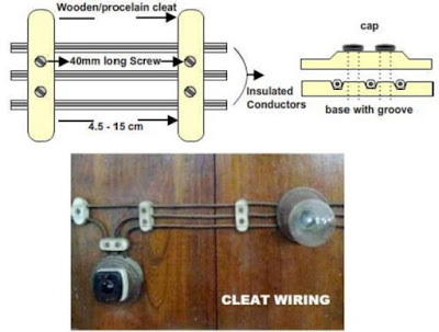
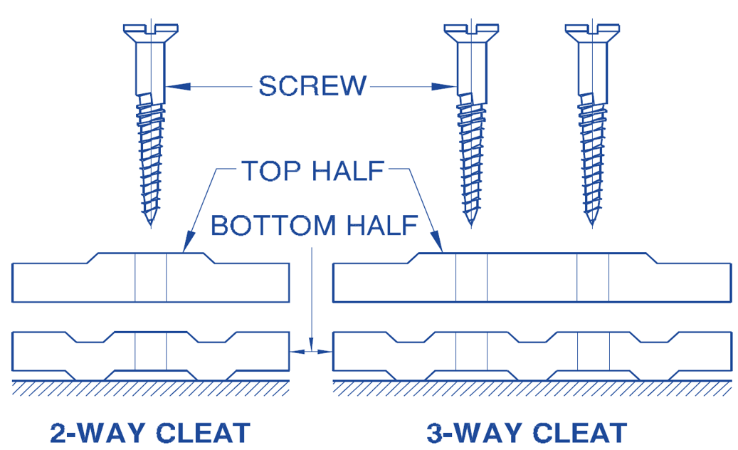
- In this system of wiring, cables are supported and gripped between porcelain cleats 6mm above the wall or roof(ceiling).
- The porcelain cleat is made in 2 parts. The main part is base, which is grooved to accommodate the cables, the other part is the cap which is put over the base.
- After placing cables or wire between the lower cleat and upper cover they are screwed on wooden plugs
- Cleats are placed above the wall or roof at an interval of 30 to 60 cm.
- The cables recommended for this type of wiring are VIR or PVC cables and any other approved insulated cables.
Advantages
- It is the cheapest system.
- Installation and dismantling is easy.
- Less skilled persons are required.
- Inspection work is easy.
- Most suitable for temporary use.
- Customization can be easily done in this wiring system e.g. alteration and addition.
Disadvantages
- It is purely temporary wiring system.
- Appearance is not good.
- Cables are exposed to atmosphere and there is a possibility of mechanical injury.
- This system should not be used in damp places otherwise insulation gets damaged.
- It can be used on 220/440 Volts on low temperature.
2.Casing and Capping Wiring
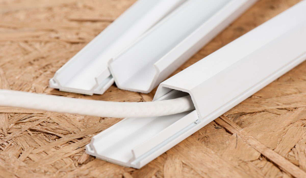
- It consists of rectangular blocks made from either seasoned and knots free wood (preferably teakwood) or PVC. But now a days PVC casing is preffered.
- The casing has usually two (or three) ‘U’ shaped grooves, into which the VIR or PVC cables are laid in such a way that the opposite polarity cables are laid in different grooves.
- The casing is covered by means of a rectangular strip of the same width as that of casing known as capping and is screwed to it.
- This system of wiring is suitable for low voltage installations.
Advantages
- It provides good insulation as conductors are apart.
- It provides good mechanical strength.
- Easy to inspect by just opening the capping.
- It is cheap in coast as compared to conduit wiring.
Disadvantages
- It is costly system nowadays because it needs seasoned, knot free wood.
- There is high risk of fire.
- The labor cost is more because it requires skilled carpenters.
- This system can not be used in damp places.
3. Batten Wiring
CTS or TRS or PVC Sheath Wiring
- CTS cables are available in single-core, twin-core or three-core with a circular or oval in shape.
- CTS cables are sufficiently chemical proof, water proof, steam proof.
- The cables are run or carried on well seasoned, perfectly straight and well varnished (on all four sides) teak wood batten of thickness 10 mm. at least.
- The width of the batten depends upon the number and size of cables to be carried by it. Battens are fixed to the walls or ceilings by means of gutties or wooden plugs.
- The cables are held on the wooden batten by means of tinned brass link clips spaced at an interval of 10 cm.
- .This system is suitable for low voltage installations.
Advantages
- It’s appearance is good, if carried properly.
- It’s life is sufficiently long.
- It can withstand the action of most chemicals such as acids and alkalies.
- It’s installation is easy and quick compared to casing capping.
- It is cheap compared to casing – capping, metal conduit and lead sheathed wiring.
Disadvantages
- This system of wiring is not recommended in situations exposed to sun and rain, unless preventive steps are taken.
- It can not be used in damp places.
- Good work man ship is required to make a sound job.
- Only suitable below then 250V.
Metal Sheathed Wiring
- In lead sheathed or metal sheathed wiring the cables used are insulated wires, TRS or PVC, with metal outer covering of about 1 mm. thick. The metal covering is known as sheathing and is made of lead – aluminium alloy containing about 95% of lead. The metal sheathed cables are run on wooden batten and are fixed to it by link – clips. The whole metal sheathing efficiently earthed as per IS732-1983
Advantages
- It provides protection against mechanical injury.
- It can be used in damp situations.
- It can be used in situations exposed to-sun, and rain provided no joint is exposed.
- It has longer life.
Disadvantages
- It is costly system of wiring.
- It is not suitable where chemical (acids and alkalies) corrosion may occur.
- In case of insulation damage, the metal sheath become alive and gives shock.
4. Conduit Wiring System
Conduit wiring system consists of either VIR or PVC cables taken through tubes or pipes and terminated at the outlets or switches / sockets. The tube or pipe is known as “conduit”. Conduit wiring may run over the surface of the walls and ceiling or may be concealed under masonary work.
Types of Conduits
- Rigid steel / metal conduit.
- Rigid PVC / non-metallic conduit.
- Flexible steel conduit.
- Flexible PVC / non-metallic conduit.
Surface Conduit Wiring
- All steel conduits should be coated or finished with galvanized or enameled surface. Conduit accessories must be of threaded type. No steel conduit less than 12.7 mm. in diameter should be used.
- The conduit should be laid over the wooden gutties, and should be fixed to the wall by means of saddles at an interval of not more than 1.2m.
Concealed Conduit Wiring
The conduits (metal or PVC) are embedded along walls or ceiling in plaster at the time of building construction. The conduits are fixed by means of saddles not more than 60 cm. apart. The VIR or PVC cables are drawn into the concealed by means of GI wire of size 18 SWG.
PVC conduits are increasingly being used in place of steel conduits. PVC conduits are less expensive and the labour time saved may be as much as 25% to 50% compared to the time taken when installing steel conduits. PVC conduits are resistant to acids alkalies, oil and moisture.
Advantages
- It provides protection against mechanical damage.
- Metal conduits provides protection against fire due to short circuit etc.
- The whole system is water proof.
- It’s life is long.
- Replacement of defective wiring is easy.
- It is shock proof if earthing is done properly.
- PVC conduit wiring (particularly concealed) is cheap.
- PVC conduit wiring requires less time.
- Concealed conduit wiring appearance is very good.
Disadvantages
- PVC conduit does not provide protection against fire.
- Metal conduit wiring is very costly.
- Metal conduit wiring requires more time.
- Metal conduit wiring needs skilled labour.
- Very hard to find the defects in the wiring.
- Very complicated to manage additional connection in the future.
Flexible conduit wiring
- It is a pipe which can be bend or twisted without damage and change in its diameter.
- It is used where the wires are to be banned and twisted several times before final connection.
- Flexible conduit are not used for general electrical wiring system.
- it is used for connecting conduits with machine terminal box in case of motor winring, energy metre in industry,etc
General Rules for Wiring
The following general rules should be kept in mind while executing the electrical wiring work:
- All conductor should be of copper or aluminium and their CSA should be according to the maximum current flowing through it.
- The current rating of the cable should be slightly greater (at least 1.5 times) than the load current.
- No switch or fuse is used in earth or neutral conductor.
- All switches which is to be used should be connected with live wire only.
- All the load installation should be in parallel connection and supplied at same voltage.
- The wiring throughout the installations should be such that there is no break in neutral wire.
- Sub distribution box should be located near the load Centre so as to minimise the length of the wire, required for wiring
- Size of earth conductor should not be less than 14 swg (standard wire gage) . The earth wire and Earth electrode should be of same material.
- Every phase(live) wire should be protected by a fuse of suitable rating as per load requirements.
- Every sub-circuit should be connected with the fuse distribution board.
- All metal coverings used for the protection of earth must be connected to earth.
- Every apparatus should be provided with a separate switch.
- No additional load should be connected to the existing installation until it has been satisfied that the installation can safely carry the additional load.
- All the switches and starters should be accessible to the operator.
- In any building light wiring and power wiring should be kept separately.
- When the installation has been completed it should be tested before giving the supply and the leakage in the wiring should not exceed 1/5000 of the maximum current of the load.
- In 3-phase, 4 – wire installation the load should be distributed almost equally on all the phases.
- In case of 3-phse, 4-wire system, at the main board, indication should be done in Red, Yellow and Blue. Neutral should be indicated in black.
- A caution notice (danger plate) should be fixed on very equipment.
Load calculation & sizing of wire:
Distribution Board:

- A distribution board is the main electrical supply system for any commercial or residential entity.
- The main cable comes into the distribution board and then get distributed via breakers to the secondary circuits such as lights and plugs.
- Distribution board is a set of MCBs, ELCBs/RCCBs which are installed in ametal box & is used to distribute distribute electrical electrical power to different loads.
Energy Meter
Not be less than 1.5 the ground level but should be at the sufficient height the supply authority is responsible for providing and maintaining the energy meter and the location of energy metre
Main switch board
It should be located adjacent to energy meter at a height of 1.5 above the ground floor. Main switch board is provided with DPIC or MCB of proper rating.
Main distribution board
It is located at such a place in the house from which the length of wire to various sub distribution box board is minimum. Its function is to energize the different sub distribution board.
Sub distribution board
It provide in the house for various lighting switches fan switches/ socket outlet with its the control switches.
Electrical Energy Distribution Systems
- As per the recommendations of ISI the maximum number of points of lights, fans and socket outlets cannot be exceed beyond 10 and the maximum load that can be connected in such a circuit is 800 watt. Hence in case of more load or more points to be connected to the supply system, then it is to be done by having more than one circuit through
- Distribution board system
- Tree system
- Joint box system
- loop – in – system.
Protection Devices:
- When a failure occurs on any part of the electrical power system, it must be quickly detected and disconnected from the system.
- If the fault not cleared quickly , it may cause unnecessary interruption of the service to the customer.
- Rapid disconnection of faulty apparatus limit the amount of damage to it and prevent the effects of fault from spreading into the system.
- The detection of fault and disconnection of faulty part can be achieved by using fuses or relays in connection with circuit breakers.
Fuse:
- The fuse is a device which is used to protect the device from a current which is too high.
- It consist of a small piece of metal and is connected in series with the circuit
- When the flow of current through a fuse huge exceeds the predetermined value then the metal melts to interrupt the circuit current and protect the circuit.
- It is not able to make or break the circuit under normal condition
- The part of the fuse which is melt during the faulty condition is called fuse element or fuse wire.
- The most commonly used material for Fuse element are lead, copper, tin zinc, and silver.
- Fuge can be Connected in live wire or neutral wire but it should be connected in live wire.
- Fuse acts as a protective device but switch does not.
Circuit Breaker:
When any fault occurs in the power system than that part of the power system must be isolated from the remaining healthy part of the system
Thus a circuit breaker will make or break a circuit either manually or automatically for different condition such as no load, full load, or short circuit condition
Relay:
Relay is a device that detect the fault and initiate a command to the circuit breaker to isolate the faulty element from the rest of the system.
Earthing System Calculation:
Calculation of the cross section of earthing conductors based on IEEE standards 80-2000

A – earthing conductor cross section in mm²
I – rms current in kA
TCAP – thermal capacity per unit volume in J/(cm³ °C)
tc – duration of current in s
αr – thermal coefficient of resistivity in 1/°C
ρr – resistivity of the ground conductor in mΩ-cm
Ko – 1/α o or (1/α r) – Tr in °C
Tm – maximum allowable temperature in °C
Ta – ambient temperature in °C
General Requirements of Electrical Installation
- Layout wiring
- Conductors
- Rating of lamp, fan and socket outlet point
- Joint box and looping in system
- Reception and distribution of main supply
- Arrangement of apparatus on switchboards
- Single phase supply
- Three phase, four wire supply
- Sub distribution board
- Sub circuits
- Diversity
- Diversity factor for sub circuit
Estimating and Costing of Electrical Installation
- Quantity and specification of material
- Price list
- Labour charges
- Overhead charges
- Contingencies
- Profit purchase system
Electrical Installations for Residential building: Estimating and Costing of Material
- Choice of particular type of wiring depending upon a particular use, financial implication and personal preferences.
- Installation work should be as per Indian Electricity Rules 1956.
- The planning and designing of electrical wiring should be done before civil work start.
- Layout of electrical wiring prepare in advance and handed over the civil engineer to make necessary provisions in the building for electric work.
Electrical Installations for Commercial Building
Electric service and supply
- Supply authority supplies power to the consumer through low voltage i.e. 415V/240V three phase four wire distribution
- Large consumers are supplied at higher voltage: 6.6, 11, 33 kV three wire high voltage feeder
Internal Distribution
- Small residential installation
- Medium Large Installation
- Large Installation